
* In the 1980s, following experiments with demonstrators for short-field transport aircraft in the 1970s, the US Air Force began development of a new large military transport, which would emerge as the McDonnell-Douglas, later Boeing, "C-17" in the 1990s. The USAF would acquire a large fleet of C-17s, with a number of export users obtaining it as well. This document provides a history and description of the C-17. A list of illustration credits is provided at the end.
* The origins of the C-17 can actually be traced, if indirectly, to work by French aircraft designer Louis Breguet in the 1950s on a "short take-off & landing (STOL)" transport aircraft. To explore his concepts, following construction of subscale models, Breguet's firm built the "Breguet 940 Integral" demonstrator, which performed its initial flight on 21 May 1958. Louis Breguet did not live to see it fly, having died in 1955 after a life of distinction as one of the pioneers of aviation.
The Breguet 940 was a boxy aircraft of modest size for a cargolifter, with a length of 15.2 meters (50 feet), a wingspan of 18 meters (59 feet), and a loaded weight of 7,710 kilograms (17,000 pounds). It had a high-mounted straight wing, an upraised tail with a loading ramp, a twin-fin tail, and fixed tricycle landing gear. It was powered by four Turbomeca Turmo II turboprop engines providing 300 kW (400 SHP) each, with a power coupling scheme linking all four engines to ensure uniform power settings, and so that one could fail without shutting down its prop. The inboard and outboard engines rotated in opposite directions to cancel torque. The wing had oversized slotted flaps across the rear. The turboprops were positioned uniformly along the wing, the outboard engines being near the wingtips, ensuring that the flaps were fully blown by the engines during take-offs and landings.
STOL performance with this "blown wing" arrangement was excellent, and so in early 1960, the French government ordered a prototype of a full-scale derivative, the "Breguet 941". Initial flight was on 1 June 1961. The Breguet 941 had very generally the same configuration as the Breguet 940 -- boxy fuselage, tail with loading ramp, high wing with four turboprop engines and extensive rear flaps -- but it was well bigger, with over twice the loaded weight; had a single-fin tail with a forward fin fillet; and proper retractable landing gear. Powerplants were the Turmo IIID, each engine with 930 kW (1,250 SHP). The machine had retractable tricycle landing gear, all gear assemblies having twin wheels; the main gear wheels were in tandem and retracted into sponsons alongside the fuselage, being semi-exposed after retraction.
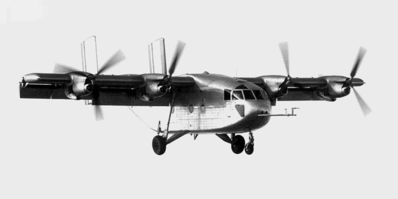
The Breguet 941 was refined into the "Breguet 941S", which was longer, featuring a radar nose, and had more powerful Turmo IIID3 engines with 1,120 kW (1,500 SHP). It could carry 40 fully equipped troops, or 24 stretchers along with medical attendants. Initial flight was on 19 April 1967, with four built, to serve with the Armee de l'Air, the French Air Force, into the mid-1970s. Two of them survive on static display. Incidentally, photos of the 941S coming in for a landing seem to show it about to crash, but with flaps deployed it had a strong "nose down" orientation, and it was actually flying much closer to the level.
   ___________________________________________________________________

   BREGUET 941S:
   ___________________________________________________________________

   wingspan:
     23.4 meters (76 feet 4 inches)
   wing area:
     83.8 sq_meters (902 sq_feet)
   length:
     23.75 meters (77 feet 11 inches)
   height:
     9.65 meters (55 feet 1 inch)

   empty weight:
     13,460 kilograms (29,610 pounds)
   MTO weight:
     26,500 kilograms (58,420 pounds)

   max speed:
     450 KPH (280 MPH / 240 KT)
   take-off run, laden:
     185 meters (610 feet)
   service ceiling:
     9,500 meters (31,200 feet)
   range:
     1,000 KM (620 MI / 540 NMI)

   ___________________________________________________________________
There was also design work towards a "Breguet 942", with an airliner fuselage for commercial operations, and a "Breguet 945", cut down in size and with twin Turmo engines, for tactical operations. Neither ever flew: as was often the problem with STOL machines, their added utility was not seen as enough to compensate for their higher cost. The idea of operating airliners out of a large number of small airports was also of questionable practicality, in an era of largely manual air traffic control.
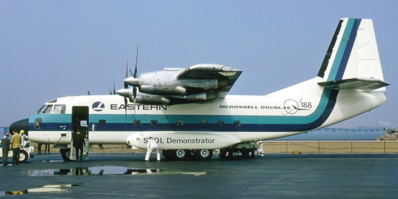
Breguet worked with the McDonnell company of the US on a license production deal, with McDonnell flying the Breguet 941S on demonstration flights in company colors in 1964, the machine being designated the "McDonnell 188" for the exercise, which targeted military users. The aircraft was damaged during one demonstration, being brought back up to flight status after eight months of work.
The second Brequet 941S machine was similarly demonstrated in 1967 as the "McDonnell 188E" -- this time around targeting commercial users, the machine flying in American Airlines and Eastern Airlines colors. It was also damaged and repaired, the repair exercises giving McDonnell engineers a good understanding of the engineering of the machine. McDonnell and Douglas merged in that year to become "McDonnell-Douglas". Nothing came of the exercise at the time, but MDD engineers got a lot of ideas about how to build a STOL aircraft that they would put to use later.
BACK_TO_TOP* In 1971, the US Air Force Tactical Air Command decided to initiate a competition for a new tactical cargolifter with STOL capability to replace the C-130 Hercules. The effort was given the designation "Advanced Medium STOL Transport (AMST)". The proposal stipulated an operational radius of 930 kilometers (575 miles / 500 NMI) with a 12,000-kilogram (27,000-pound) payload, operating off a rough airstrip with a length of 610 meters (2,000 feet). That was half the field length for a C-130.
Five US aircraft companies submitted proposals for the AMST, with Boeing and McDonnell Douglas selected to each build two prototypes for evaluation. The Boeing entry, the "Model 953", had twin engines; it was given the military designation of "YC-14". The MDD entry, the "YC-15", had four engines. The YC-15 beat the YC-14 into the air, the first YC-15 prototype performing its initial flight on 16 August 1975, the second getting into the air in December. Initial flight of the first YC-14 prototype was on 9 August 1976, the second becoming available before the beginning of trials at Edwards Air Force base in November 1976. The program stretchout was due to funding cuts to AMST.
* The YC-14 had a configuration with many similarities to other jet cargolifters, with a wide body; main landing gear mounted in fuselage sponsons to prevent obstruction of the cargo bay; a high-mounted wing plus a tee tail; and a high tail with doors and a loading ramp, the doors capable of being opened in flight for airdrops. Where it significantly differed was in the mounting of its twin turbofan engines above and well forward of the wing, with the exhaust from the engines blown over the wing to improve lift and short-field capability, a scheme known as "upper surface blowing (USB)".
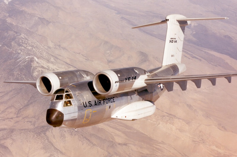
The YC-14 featured a straight wing and tailplane, the tailplane mounted on a swept tailfin. The wing had a "supercritical" airfoil section, which managed to achieve good flight efficiencies at high and low speeds, and was particularly well-suited to a cargolifter. The aircraft was powered by twin General Electric (GE) CF6-50D turbofans, with 227 kN (23,120 kgp / 51,000 lbf) thrust each and thrust reversers. The "overwing" configuration also helped reduce the aircraft's infrared signature, lowering its vulnerability to surface-to-air missiles (SAM).
The nose gear had twin wheels and apparently retracted forward; each main gear assembly having four wheels in a 2x2 configuration and retracting upward sponsons into its stowage. The C-17 could carry up to 150 troops or 31,400 kilograms (69,400 pounds) of cargo, though the load was limited to 12,300 kilograms (27,000 pounds), as above, to meet short-field spec. There was a crew door on the left front fuselage; if there were any other doors besides the tail doors, it is unclear where they were.
   ___________________________________________________________________

   BOEING YC-14:
   ___________________________________________________________________

   wingspan:
     39.32 meters (129 feet)
   wing area:
     163.7 sq_meters (1,762 sq_feet)
   length:
     40.14 meters (131 feet 8 inches)
   height:
     14.68 meters (48 feet 2 inches)

   empty weight:
     53,410 kilograms (117,500 pounds)
   MTO weight:
     113,375 kilograms (250,000 pounds)

   max speed:
     800 KPH (500 MPH / 435 KT)
   service ceiling:
     13,700 meters (45,000 feet)
   range, STOL spec:
     930 KM (575 MI / 500 NMI)

   ___________________________________________________________________
* The YC-15 was of similar size to the YC-14 and had a broadly comparable configuration -- the greatest difference being, as mentioned, four engines, mounted under the wing. The powerplants were Pratt & Whitney (P&W) JT8D-17 turbofans, used on the Boeing 727 and Douglas DC-9, with 72.5 kN (7,255 kgp / 16,000 lbf) thrust each. It leveraged off the Breguet 941S by using much the same blown flaps scheme, but otherwise the Breguet 941S was no more than a source of inspiration for the YC-15 design.
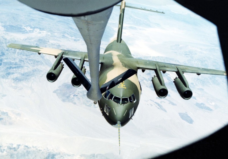
The YC-15 otherwise shared a substantial amount with the YC-14, featuring a high-mounted straight supercritical wing and tailplane; swept tailfin; tricycle landing gear, two wheels on the nose gear, four wheels in 2x2 configuration for each main gear assembly, the main gear retracting into sponsons alongside the fuselage; high tail with tail doors and loading ramp; and crew door on the left forward fuselage. Again, if there were other doors, it's unclear where they were. Subsystems for the YC-15 were scavenged from a wide variety of other aircraft. Since the YC-14 and YC-15 were designed to the same spec, of course the YC-15 had similar load specifications as the YC-14.
   ___________________________________________________________________

   MDD YC-15:
   ___________________________________________________________________

   wingspan (demonstrator #72-1875):
     40.4 meters (132 feet 7 inches)
   wingspan (demonstrator #72-1876):
     33.6 meters (110 feet 4 inches)
   wing area:
     162 sq_meters (1,740 sq_feet)
   length:
     37.9 meters (124 feet 3 inches)
   height:
     13.2 meters (43 feet 4 inches)

   empty weight:
     47,600 kilograms (105,000 pounds)
   MTO weight:
     98,285 kilograms (216,680 pounds)

   max speed:
     860 KPH (535 MPH / 465 KT)
   service ceiling:
     13,700 meters (45,000 feet)
   range, STOL spec:
     930 KM (575 MI / 500 NMI)

   ___________________________________________________________________
Trials of the YC-14 and YC-15 went on into 1977, both aircraft meeting spec, after some tweaking, for the AMST program. However, then the Air Force decided that the service needed airlifters for both the tactical and strategic roles, and the AMST demonstrators didn't look like a good fit. The Air Force cancelled the AMST program and neither aircraft was put into production. The Soviet Antonov design bureau did design a transport designated the "An-72" that also used the high-engine configuration of the Boeing YC-14.
The YC-14s and YC-15s were put into storage at the "boneyard" at Davis-Monthan Air Force Base (AFB) in Arizona; one each ended up at the nearby Pima Air Museum. The YC-15 at the museum was later refurbished by MDD for trials, taking to the air again in 1997; it was badly damaged by an inflight engine failure the next year, and didn't fly again. It eventually ended up on display at Edwards Air Force base, while the other YC-15 was scrapped. At last notice, both YC-14s were still in existence, though they had clearly seen better days.
BACK_TO_TOP* The YC-15 would lead to something bigger and better. In the wake of the cancellation of AMST, in February 1980 the USAF issued a "C-X" requirement for a heavy tactical transport to replace the Lockheed C-141 Starlifter. Boeing, Lockheed, and McDonnell Douglas submitted proposals, the Boeing submission being along the lines of an enlarged YC-14 with a third engine in the tail, with Lockheed proposing a derivative of the company's L-1011 Tristar jetliner, as well as a beefed-up C-141 derivative.
The McDonnell Douglas submission, which was clearly derived from the YC-15 but was scaled up and had many changes, was declared the winner in August 1981. However, the program then stalled, since the USAF was diverted in their transport plans by a 1982 decision to buy 50 new-build Lockheed C-5B heavy lifters, as well as 44 (later 60) McDonnell Douglas KC-10 Extender tanker / cargolifter variants of the company's DC-10-30CF commercial airliner.
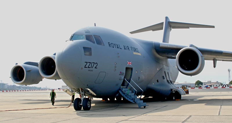
The requirement for a tactical airlifter didn't go away, and in September 1983 a new Air Force "Master Airlift Plan" committed the service to high-priority development of the McDonnell Douglas "C-17A Globemaster III", as the new transport had become known, with first flight in August 1990 and a planned total buy of 210 machines. Unfortunately, the zigs and zags of the program didn't go away either, with construction of the sole "T-1" flight prototype deferred until November 1987, first flight following on 15 September 1991, over a year behind schedule, with test pilot William Casey in the driver's seat. Incidentally, there were also two static-test prototypes, "T-2" and "T-3".
The first "P-1" production machine performed its initial flight on 18 May 1992; the first five production machines were used for trials, to be passed on to operational service after trials were completed. At the time of the first flight of P-1, the total buy had been scaled back to 120 aircraft; a year later, the buy was scaled back to 40 machines, with the program placed on probation. The type went into service in 1994 -- to then hit another snag, when a static test airframe suffered a wing structural failure. The fleet was grounded, with fixes applied to existing aircraft and a modified wing flowed into production, the flaps also being updated because they didn't bear up under hot engine exhaust.
That was not the instant end of the difficulties, but the program then converged towards maturity -- everyone working together instead of against each other, with the C-17 finally proving highly satisfactory in service. The T-1 prototype, incidentally, remained in service as a trials machine up to 2012, being retired to the USAF Museum at Wright-Patterson AFB in Ohio. It was also used as a movie prop, appearing in five films including two TRANSFORMERS movies, two IRON MAN movies, and a SUPERMAN movie. Boeing's buyout of McDonnell Douglas in 1997 means that the aircraft is now the Boeing C-17 -- MDD having suffered the hardships on the C-17 program, Boeing was in a position to reap the rewards.
Of course, crews had no particular fondness for the stilted name of "Globemaster III", and it became best known as the "Mighty Moose" or more typically just "Moose" -- one mass C-17 exercise being designated Operation FURIOUS MOOSE. Other nicknames included "Buddha", the aircraft being short, fat, and revered; and "Barney", a mixed tribute to the classic FLINTSTONES caveman cartoon show and the bigger C-5A Galaxy, known as the FRED (more or less meaning "Fantastic Ridiculous Economic Disaster"), Barney Rubble being Fred Flintstone's smaller sidekick.
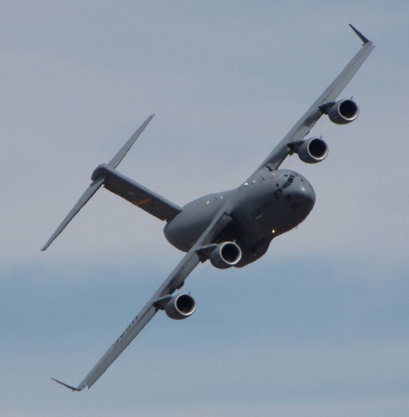
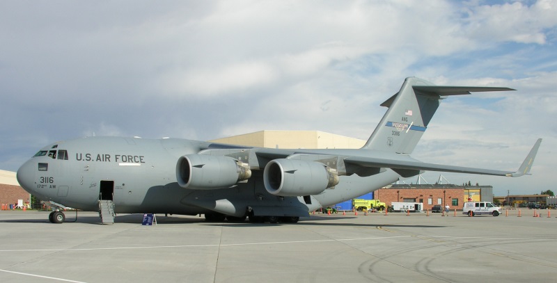
BACK_TO_TOP* As introduced, the C-17 was a big, voluminous aircraft, made mostly of aircraft aluminum alloy, with some titanium and composite assemblies. As mentioned, the C-17 had similarities to the older YC-15, featuring a high wing with four engines mounted on pylons underneath, a tee tail, main gear in sponsons, and a tail loading ramp. One major difference, aside from size, was that the C-17 had swept flight surfaces, while the YC-15 had straight flight surfaces. There was a fair resemblance between the YC-15 and the C-17 on a level view; not so much resemblance on a top view.
Each of the C-17's wings featured a 25 degree sweepback, supercritical airfoil section; large double slotted flaps in two sections; an aileron outboard of the flaps; four spoilers ahead of the flaps; full-span leading-edge slats, and a wingtip winglet. The flaps used "propulsive lift" as per the YC-15, with engine exhaust flowing above and below the extended flaps, reducing take-off run. The spoilers were used for roll control -- only the inboard spoilers were deployed at high speed, to prevent overstressing the airframe -- as well as lift enhancement at low speed, and as lift dumpers / airbrakes on landings. The tee tail had a split rudder and variable-incidence tailplane; there was a fixed strake along each lower side of the tail.
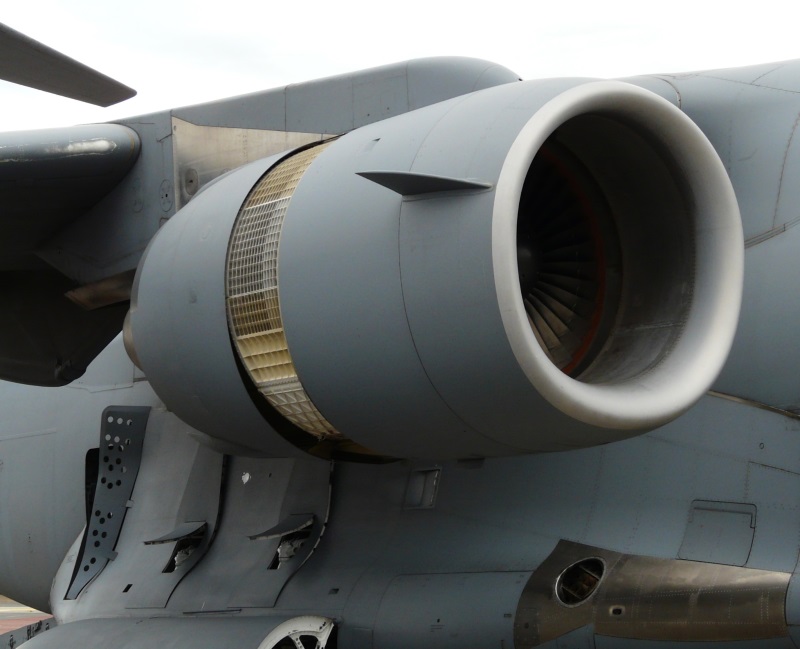
The C-17 was powered by four Pratt & Whitney F117-P-100 high-bypass turbofans with 185.5 kN (18,915 kg / 41,700 lb) thrust each, similar to the commercial P&W P2040 turbofans used on the Boeing 757 jetliner. The engines had thrust reversers to reduce landing roll and for ground handling, with the aircraft able to back up a shallow slope. The thrust reversers deflected the thrust upwards, and so the engines could remain powered up while the aircraft was being quickly unloaded -- allowing it to take off again immediately once unloading was complete. There were two distinctive little fins on each upper engine cowling, acting as "vortex generators" to ensure airflow over the wing and delay onset of stall at high angles of attack.
A Honeywell auxiliary power unit (APU) turbine was fitted in the front of the right main landing gear sponson to provide engine starting and ground power; a "ram air turbine" would be extended from the right sponson in the case of a comprehensive power failure, to provide hydraulic system power for minimal flight control. There were six fuel tanks in the wings, with a total capacity of 102,614 liters (27,108 US gallons), and an inflight refueling socket behind the cockpit. An inert-gas generation system helped reduce fuel system fires or explosions. In later production, at least some C-17s were fitted with a wing center-section tank with a capacity of 36,340 liters (9,600 US gallons) of fuel, these aircraft being informally designated as "C-17 ER". It is unclear if all C-17s were eventually kitted up to ER specification.
The nose landing gear had two wheels, while each of the two main gear assemblies had six wheels in two rows of three. The nose gear retracted forward and was steerable by rudder pedals, as well as a tiller for tight ground maneuvering. The main gear extended straight down from its sponsons; all landing gear assemblies would open by gravity in case of system failure. The robust landing gear could support steep-angle combat zone landings.
   ___________________________________________________________________

   BOEING C-17:
   ___________________________________________________________________

   wingspan:
     52.20 meters (171 feet 3 inches)
   wing area:
     353.02 sq_meters (3,800 sq_feet)
   length:
     53.04 meters (174 feet)
   height:
     16.79 meters (55 feet 1 inch)

   empty weight:
     122,015 kilograms (269,000 pounds)
   MTO weight:
     263,085 kilograms (580,000 pounds)

   max cruise speed:
     830 KPH (515 MPH / 445 KT)
   service ceiling:
     13,715 meters (45,000 feet)
   range with payload:
     5,190 KM (3,225 MI / 2,805 NMI)

   ___________________________________________________________________
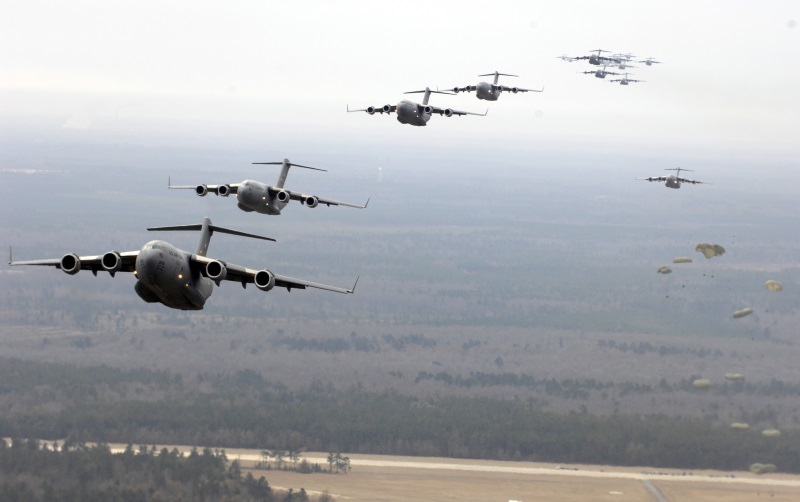
Normal crew consisted of two pilots and a loadmaster, with seats for two more cockpit crew as cockpit observers. The C-17 had a "glass cockpit" with four displays, plus a "head-up display (HUD)" for each pilot. The aircraft featured a quadruplex fly-by-wire flight control system; the pilots used sticks and not yokes. Avionics included radios, radio navigation and landing systems, identification friend or foe (IFF) transponder, and a weather radar in the nose. One particularly interesting item of avionics kit was a "Formation Flight System" that allows C-17s to perform mass airdrops in zero visibility with no great hazard of collision.
The C-17 was equipped with an onboard oxygen generator system (OBOGS) to eliminate the need for stocking oxygen bottles. There was s also a fire extinguishing system, but though it can be assumed it protected the engines, details are unclear. The C-17 had defensive countermeasures, featuring threat-warning receivers and chaff-flare dispensers. There was a rest area behind the cockpit on the upper deck, with two bunks and two seats; the upper deck also featured a galley and a lavatory. The loadmaster had a workstation under the rest area in the lower deck.
There was an "airstair" door for the crew on the left front of the aircraft into the lower deck, with a matching emergency exit door on the right, and a hatch on top of the cockpit upper deck for emergency escape. There were roll-up doors on each side of the rear fuselage for parajumping, with a deployable screen ahead of each door. There were two hatches on top forward of the wing box, and two similar hatches behind the parajump doors, for emergency escape. The tail door assembly had two sections, the top section hinging up into the payload bay, the lower ramp section hinging down.
The cargo bay had a length of 20.78 meters (68 feet 2 inches), a height under the wing center section is 3.76 meters (12 feet 4 inches), and a maximum useful width of 5.49 meters (18 feet). There was a load-handling system, including rollers, running the full length of the cargo bay. There were 17 tip-up seats along each side of the cargo bay, and 48 more seats could be installed in the center of the cargo bay, providing seats for 102 fully-equipped troops; pallets providing 100 seats could be installed as an alternative, giving 154 seats. Another option was installation of 48 stretchers in place of the center seats. The fuselage was as wide as that of a C-5 Galaxy, and cargo loads could include:
Absolute maximum payload was 78,100 kilograms (172,200 pounds), but a typical payload was 56,250 kilograms (124,000 pounds), with a heavy operational payload running to 69,535 kilograms (153,300 pounds). The C-17 could carry 18 times the payload of the classic C-47 / DC-3 -- which, considering the modest size of the C-47, was not so impressive -- but the C-17 could take off from and land on shorter runways, which was very impressive. The C-17 had excellent short-field capability and proved surprisingly agile for an aircraft of its size, performance being well superior to its predecessor cargolifters in USAF service. It established a number of records in its class and would prove a muscular ride when unladen, compared at least in some respects to flying a fighter jet.
BACK_TO_TOP* The C-17 provided good service in the Balkan interventions in the late 1990s, and also performed logistics flights to Antarctic research installations. It fully came into its own after the terrorist attacks on the USA on 11 September 2001, proving a significant asset in the "Global War On Terror", with acquisition of the big aircraft stepping up in pace. It saw intensive use in the Afghanistan intervention from 2001 and the invasion of Iraq in 2003. On 26 March 2003, a Moose flight paradropped troops to capture Bashur Airfield in northern Iraq, and followed up the initial drop to install an entire combat brigade there in only 62 sorties.
C-17s also airdropped millions of humanitarian daily rations for relief of starving civilians in these theaters. One C-17 was hit by a SAM after departing Baghdad Airport on 9 December 2003; it returned to the airport and was repaired. In 2021, C-17s from several nations participated in the emergency airlift out of Kabul, Afghanistan, with tens of thousands evacuated.
The Air Force ended up acquiring a fleet of 223 C-17s, not counting the prototype and including an attrition replacement -- for an aircraft lost with its crew of four during a training flight in Alaska in 2010. The last USAF Moose was delivered in 2013. The quantity was a clear vindication of the type, being a dozen more machines than was projected at the outset, which is not to dismiss the problems with the development program. The C-17 has been enhanced over the course of production, with items including:
Now that all C-17s have been delivered to the Air Force, the service wants to make sure they are all kept up to as common a configuration standard as possible. Having updated the avionics to a modern standard, software updates are provided every now and then -- with less-frequent updates to the cockpit avionics and mission processor, primarily to deal with parts obsolescence. There have been ongoing improvements in procedures, particularly to reduce fuel consumption -- for example, more precise load planning to ensure optimum center of gravity, and the use of ground power carts instead of the APU except when it's needed.
The USAF configured a number of C-17s as "Special Operations Low Level (SOLL) II" machines for special operations, to replace C-141B Starlifters that had been modified for the SOLL II role. Exact details remain classified, but the C-141B SOLL II machines hint that the C-17 SOLL II aircraft had an imaging turret under the nose; they may have also had enhancements to lighting, communications, and defensive countermeasures. It is tempting to think they had offensive armament as well, such as an ability to dispense smart munitions, but no cause to think they do. Incidentally, "SOLL II" does not mean "second series SOLL machine", it defines a mission: SOLL I being daylight low-level operations, and SOLL II being night low-level operations
The C-17 also ended up being used as VIP transport, being fitted with the "Silver Bullet Command & Control" module, base on commercial Airstream trailers. Two Silver Bullet modules were built, but after about two decades of use, doubts arose as to their safety -- and they will be replaced by "Roll-On Conference Capsule (ROCC)" in the not-too-distant future.
In 2013, on the occasion of the last C-17 delivery to the USAF, an Air Force spokeswoman announced that from 11 September 2001 to 4 September 2013, the service's C-17s had flown more than 550,000 sorties adding up to about two million flying hours, carrying almost six million passengers and 3.6 million tonnes (4 million tons) of cargo. From 2006 to that time, they had dropped more than 84,000 parachute loads amounting to 60,000 tonnes (66,000 tons) of materiel. Mission-capable rate in the previous six years was an outstanding 84%+. The Air Force can expect much more good service from the C-17 until it's finally replaced -- no doubt, given expectations that the problem of fuel availability isn't likely to go away, by a much more fuel-efficient cargolifter. Right now, the C-17 is expected to fly into the 2050s.
* There were a fair number of export orders for the C-17:
It is unclear if foreign operators called the C-17 the "Moose", though it would seem the Canadians would have no problem with that nickname.
Boeing operates support for the C-17 on a "global" basis, which means in practice that any one operator can obtain spares, and to a degree assistance, from any other C-17 operator. In any case, total production of the C-17 amounted to:
-- for total production of 277 C-17s. The final C-17 was rolled out in late 2015, ten having been built with company funds on expectation of more sales; they were all sold. Boeing tried to push a stretched C-17 with uprated engines, but there were no takers. The company also tried to push a civil C-17, but that didn't happen either, the type being too expensive to operate on a commercial basis -- particularly relative to the Russian Antonov An-124 cargolifter, the literal giant of the commercial airlift market. There is the possibility that military C-17s may later get a "second life" in civil hands, but if so, it won't be for some time.
BACK_TO_TOP* Investigation has been conducted on the design of America's next jet cargolifter, the primary focus being on a more fuel-efficient aircraft. The US Air Force Research Laboratory (AFRL) has worked with American aerospace companies on the "Revolutionary Configurations for Energy Efficiency (RCEE)". The primary goal for the exercise was to obtain improved flight efficiencies for Air Force tankers and transports, which use up two-thirds of the USAF fuel budget. Along with investigations of advanced propulsion systems, RCEE considered advanced airframe designs, one of the most interesting being a "hybrid wing body (HWB)" cargolifter from Lockheed Martin, as a functionally compatible replacement for the company's C-5 heavy cargolifter.
The HWB concept looked like a "blended wing body (BWB)" aircraft -- a flying wing vaguely reminiscent of a stingray -- coupled to a C-17 aft fuselage, with a tee tail grafted onto the end, a fan-type engine being mounted above each inboard wing. The rationale for the aft fuselage was to support loading and airdrop operations, which are troublesome with pure flying wing designs. There was a cylindrical pressurized cargo hold running through the fuselage, with unpressurized side cargo bays in the wings; presumably the aircraft would be to a degree self-loading, with cargoes shuttled automatically to their assigned locations.
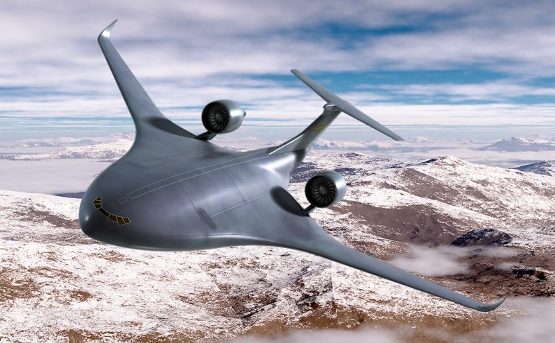
A number of engine options were considered, starting with the existing General Electric GENx turbofan, as well as future engines -- with "hybrid" systems being seen as attractive in the longer run, featuring electrically-driven fans powered by a gas turbine generator, with a battery pack to provide take-off boost power. The HWB would have good short-take-off capability and flight efficiencies 30% better than the C-5. While it was just a concept, a Lockheed Martin official pointed out that it took about two decades to field the C-17, adding: "We need to start today to avoid a future gap."
* Another study, conducted by Boeing for the AFRL, investigated a future cargolift aircraft for the Air Force, projected for the 2025:2030 timeframe, that could either fly on conventional jet fuel or liquefied natural gas (LNG).
The use of LNG to power aircraft is not a new idea; in fact, Boeing suggested the concept in a 2012 study for NASA. On further investigation, Boeing engineers concluded that by 2040, LNG aviation fuel will be 50% cheaper than "Jet A" fuel; LNG, which is essentially methane, is a very efficient fuel and also burns clean. There's a catch, however, in that LNG fuel tanks have to be large and cryogenically cooled. As a result, the Boeing study for the AFRL focused on a BWB-type configuration, with plenty of volume for both jet fuel and LNG tanks. The relatively bulky LNG tanks would add weight, but the higher efficiency of LNG would more than compensate.
Still, to keep the LNG tanks to manageable size and weight, the design study assumed that LNG would only be used to fly the aircraft the range of an average mission, or about half maximum range. The jet fuel tanks would be sized for full range; a mission could use both LNG and jet fuel for extended range. The question of range leads to the interesting question of midair refueling of LNG-powered aircraft; it sounds tricky on the face of it, and the article said nothing about it. In any case, some jet fuel would be required even if a mission was to be flown on LNG, since chilly LNG has to be vaporized to burn. Jet fuel would be used for take-offs in any case, with LNG taking over during the climb.
Fabricating reusable, lightweight cryogenic storage tanks for LNG will be a challenge. Space launch vehicles with cryogenic propulsion use insulation that's too bulky for aircraft applications; the double-walled steel "dewar" tanks used on LNG-powered vehicles are compact enough, but too heavy. Current thinking envisions LNG aircraft tanks built as dewars, using advanced lightweight materials. The cold storage of the LNG would have an advantage in providing a cooling to support aircraft systems.
The use of high-bypass turbofan engines that can burn either jet fuel or LNG is not seen as an obstacle; turbine engines are not notably picky about the fuel they use, and there are nonflying turbines that can handle dual fuels. General Electric's LM2500 power turbines, a derivative of the popular CF6 turbofan, is in use on high-speed ferries built by Incat Tasmania of Australia. LNG could of course fuel a power turbine for a hybrid aircraft.
There is the issue of LNG supply infrastructure, but LNG is becoming an established fuel, and that problem also looks likely to take care of itself. However, since the US military operates globally, dual-fuel operation seems a prudent option, allowing the Air Force to fly using either of the two fuels, as dictated by local availability and relative cost.
BACK_TO_TOP* One item that didn't quite fit into the text was the use of a C-17 in 2006 for test drops of an air-launched satellite booster named "QuickReach". A dummy QuickReach article was dropped out of the payload hold to determine the feasibility of the launch method. There were no big hangups with the drops, but the QuickReach program was canceled, and no actual launches of the booster were performed.
Another interesting little item was a test performed by the USAF in 2013, in which a C-17 riding a wingtip vortex of another C-17 showed it could cut its fuel burn by 10%. The Air Force has refined software to automate the procedure, allowing a C-17 to ride a vortex without adding to aircrew workload.
* Sources include:
Other materials were picked up from JANE'S, Wikipedia, Boeing & Airbus online materials, and the "airforce-technology.com" website.
* Illustrations details:
* Revision history:
   v1.0.0 / 01 feb 14 / Originally included Airbus A400M.
   v1.0.1 / 01 jan 16 / C-17 global support.
   v1.0.2 / 01 dec 17 / Review & polish.
   v2.0.0 / 01 nov 19 / Cut out Airbus A400M.
   v2.1.0 / 01 sep 21 / Review & polish.
   v2.1.1 / 01 aug 23 / Review & polish.
   v2.1.2 / 01 aug 25 / Review & polish. (!)
BACK_TO_TOP